Recent claims from Google of achieving “Quantum Supremacy” brought a lot of attention to the subject of Quantum Computing. As a software developer all of the sudden every non-developer person I know started asking me questions about it, what it meant, and if it’s the start of skynet 🤖
I knew only the basic stuff from college, general concepts from quantum mechanics and superposition, but barely grasped how it was actually applied to computing and algorithms. So I decided to study it more deeply and develop a weekend project along the way.
I’m sharing my learnings in this post focusing on the programmer’s perspective of quantum computing, and demystifying the almost supernatural facet the general media gives to it. It’s basically just linear algebra.
My weekend project turned out to be a pet Quantum Simulator, which I made available on github.
The Qubit
Qubit is the basic unit of quantum information. You can think of it as a variable that when measured gives you either true or false, i.e., a boolean value. For instance:
var q = new Qubit(true);

Assert.IsTrue(q.Measure());
As a variable, you can perform operations on qubits, such as applying the “X gate” to negate its value:
var q = new Qubit(true);

new XGate().Apply(q);

Assert.IsFalse(q.Measure());
Now things get more interesting, the quibit’s value, or state, can also be in a coherent superposition, being both true and false at the same time, with 50% ~ 50% probability (adding up to 100%). To achieve that we apply an “H gate” (Hadamard gate) to it:
var q = new Qubit(false);

new HGate().Apply(q);

// will print 'true' half of the time, 'false' the other half
Console.Write(q.Measure());
To understand what this means we need to take a look at the Qubit’s internal state. It’s actually an array of complex numbers. Considering a single qubit system we can have:
[1, 0]→ 100% chance of being measured 0 (false)[0, 1]→ 100% chance of being measured 1 (true)[1 / sqrt(2), 1 / sqrt(2)]→ 50% chance of being measured 0 and 50% chance of being measured 1
OBS: The correct mathematical notation of a quantum state of “n” qubits is a vector of a single column and 2n rows. Here I’m describing how to implement it in code, using arrays.
The first position of the array holds a complex number describing the probability of the qubit being “0”, and the second position of it being “1”. The probability for each outcome is calculated as the complex number magnitude squared.
Each quantum gate is a matrix that operates on the quantum system state. For example, I implemented the “H Gate” as a UnaryOperation in my project:
public class HGate : UnaryOperation
{
    protected override Complex[,] GetMatrix()
    {
        return h_matrix;
    }

    private readonly Complex[,] h_matrix = new Complex[,]
    {
        { 1 / Math.Sqrt(2), 1 / Math.Sqrt(2) },
        { 1 / Math.Sqrt(2), -1 / Math.Sqrt(2) }
    };
}
So the “H gate” took the qubit from the [1, 0] state to the [1 / sqrt(2), 1 / sqrt(2)] state through a matrix multiplication, implemented as follows:
public static Complex[] Multiply(Complex[,] matrix, Complex[] vector)
{
    if (matrix.GetLength(0) != vector.Length)
        throw new InvalidOperationException();

    var r = new Complex[vector.Length];

    for (int i = 0; i < matrix.GetLength(0); i++)
    {
        r[i] = 0;
        for (int j = 0; j < matrix.GetLength(1); j++)
            r[i] += vector[j] * matrix[i, j];
    }

    return r;
}
You can define different 2x2 matrices to operate on a single qubit, but there’s a catch, quantum gates must be reversible (due to physical world constraints), i.e., applying it twice should reverse its effects:
var q = new Qubit(false);

new HGate().Apply(q);
new HGate().Apply(q);

Assert.IsFalse(q.Measure());
This reversibility is also required for more complex quantum gates, operating on multiple qubits as we’ll see in the next section.
Quantum Entanglement
The potential of quantum computing becomes more apparent when we start using gates that operate on two or more qubits. Perhaps the most famous binary quantum gate is the “CNOT gate” (CXGate class in my project), which will negate the target qubit if a control qubit is true, otherwise it preserves the target qubit:
var control = new Qubit(true);
var target = new Qubit(false);

new CXGate().Apply(control, target);

Assert.IsTrue(target.Measure());
The “CNOT gate” defines a 4x4 matrix that is applied to the two qubit system state. Here’s how I implemented it:
public class CXGate : BinaryOperation
{
    protected override Complex[,] GetMatrix()
    {
        return cx_matrix;
    }

    private readonly Complex[,] cx_matrix = new Complex[,]
    {
        { 1, 0, 0, 0 },
        { 0, 1, 0, 0 },
        { 0, 0, 0, 1 },
        { 0, 0, 1, 0 }
    };
}
As expected the two qubit quantum system state vector will have length “4” (Length = 2n), representing four exclusive values, and superpositions of them:
[1, 0, 0, 0]→ 100% chance of being measured 0[0, 1, 0, 0]→ 100% chance of being measured 1[0, 0, 1, 0]→ 100% chance of being measured 2[0, 0, 0, 1]→ 100% chance of being measured 3
To derive the four position state vector from the two qubits, simply perform their tensor product, for instance:
[1, 0] ⦻ [0, 1] = [0, 1, 0, 0]
Which is equivalent to |0⟩ ⦻ |1⟩ = |01⟩ using Dirac notation.
Now supose that, before applying the “CXGate”, we apply the “HGate” to the control bit, what would happen?
var control = new Qubit(true);
var target = new Qubit(false);

new HGate().Apply(control);
new CXGate().Apply(control, target);

// What to expect for:
// control.Measure() ?
// target.Measure() ?
We’ve seen before that the control qubit will be in a coherent superposition state, then it will be applied to the “CXGate”, modifying the target qubit. From a classical point of view there are two valid scenarios:
- Control qubit is 0 and target qubit is preserved as 0
- Control qubit is 1 and target qubit is flipped to 1
Which one will be? Actually both of them!
If you measure one qubit (control or target - you choose), you have 50% of chance for each outcome, either 0 or 1. But after that the quantum state collapses, and we will have 100% certainty of the next measurement outcome, since there are only two valid states for this system. The value of one qubit dictates the value of the other. The qubits are entangled.
Algebraically this entangled state is describe as:
[1/sqrt(2), 0, 0, 1/sqrt(2)]→ 50% chance of being measured 0 (|00⟩) and 50% chance of being measured 3 (|11⟩)
There is no possible outcome where values 1 (|01⟩) or 2 (|10⟩) are measured.
Quantum Collapse
Measuring, or “collapsing”, a single quibit is easy, as explained above it has only two possible outcomes, each one with a defined probability. It behaves as a random variable.
As more qubits are added to the quantum system and become entangled, measuring one quibit can have a direct impact on other quibits, collapsing their probability distribution. A practical implementation for measuring a single qubit in a multiple qubit system, extracted from my Qstate class, follows:
int val = Sample();
bool m = BinaryUtility.HasBit(val, pos);
Collapse(pos, m);
Initially it samples the quantum system state vector in full, without changing it, getting an outcome for the 2n system. If we wanted to measure all system qubits at once, we could simply collapse the entire state vector from this sample, however we are only interested in measuring one qubit, leaving others unmeasured.
So after getting a full sample we test for the bit being measured. It could be present in the sample, in which case it will collapse to true, or not present, collapsing to false. Once we get its value we propagate it to the state vector:
private void Collapse(int pos, bool b)
{
    for (int i = 0; i < v.Length; i++)
        if (BinaryUtility.HasBit(i, pos) != b)
            v[i] = Complex.Zero;

    var sum = Math.Sqrt(
        v.Sum(x => x.Magnitude * x.Magnitude)
    );
    for (int i = 0; i < v.Length; i++)
        v[i] /= sum;
}
This method will zero out all positions in the state vector in which this quibit has a different value than what was measured. Then it will normalize the vector, making sure the sum of the complex numbers magnitudes squared adds to one.
From a logical point of view this is what “quantum collapse” means, we measured one qubit and propagated its value to the quantum state vector, “zeroing” the probability of all outcomes inconsistent with this measurement.
Beating Classical Computing
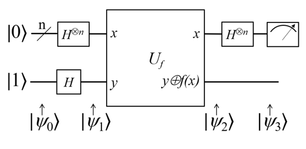
Saving the best for last, I will now introduce the Deutsch Oracle algorithm, one of the first examples of a quantum algorithm that is exponentially faster than its classical counterpart on the size of the input.
Its quantum circuit diagram is presented below:

The purpose of this algorithm is to determine if an unknown function f(x) is either balanced or constant. Considering the one quibit case (n = 1) there are two balanced functions, the identity and the negation functions:
| Input | Identity | Negation |
|---|---|---|
| 0 | 0 | 1 |
| 1 | 1 | 0 |
And two constant functions, the “set to zero” and the “set to one” functions:
| Input | Set to zero | Set to one |
|---|---|---|
| 0 | 0 | 1 |
| 1 | 0 | 1 |
The algorithm circuit will become more clear after we translate it to code, considering an unknown one qubit input function f(x) implemented by a binary quantum gate:
public class DeutschAlgorithm
{
    public bool IsBalanced(BinaryOperation gate)
    {
        var q1 = new Qubit(false);
        var q2 = new Qubit(true);

        new HGate().Apply(q1);
        new HGate().Apply(q2);

        gate.Apply(q2, q1);

        new HGate().Apply(q1);

        return q1.Measure();
    }
}
Classically we would require two measurements to find out the answer. For instance, if we query the {0 → 0} input/output pair, we are not sure yet if this is an identity or “set to zero” function.
In quantum computing however, we can find out the answer with a single query! I will not get into the details of the circuit inner workings, only say that it takes advantage of superposition to reduce the number of queries required to get a conclusive answer.
To see the math behind it open the link provided at the start of this section. You can also debug the algorithm executing one of my project unit test classes: DeutschAlgorithmTests.cs
It was really fun learning more about quantum computing and implementing a basic quantum simulator. This was a brief introduction into the subject, which I tried to keep simple, and haven’t covered quantum operations involving imaginary numbers or gone too deep into the math.
If you find any problem in my quantum simulator code feel free to open an issue on github.


